G.657.A1 vs G.657.A2
ITU-T G.657.A1 and G.657.A2 both describe bend-insensitive single-mode fibers. Most comparisons stop at one number — 10 mm versus 7.5 mm — and leave buyers with the impression that A2 is simply the better fiber.
That framing causes two expensive mistakes. Buyers over-specify A2 on long straight routes where it changes nothing, and they under-specify the variables that actually decide whether a fiber survives in a tight-wound application. This comparison covers the thuhu ar flexión difference, then the three factors that sit behind it: how bend loss is actually measured, what mechanical screening does and does not guarantee, and why coating diameter belongs in the decision.
Quick Answer: Which One Do You Need?
| Your application | Specify | Why |
|---|---|---|
| Long straight runs, outdoor distribution, standard FTTH drop | G.657.A1 | 10 mm allowance covers routine routing; A2 adds cost without changing outcomes |
| Compact enclosures, high-density panels, tight-wound spools | G.657.A2 | 7.5 mm design allowance plus tighter attenuation limits |
| Bend radius below 7.5 milímetro | Neither — look at G.657.B3 | Both A-category grades are specified above that range |
One question settles most cases: what is the smallest bend radius your design actually forces on the fiber? If nothing in the route goes below 10 milímetro, A1 is the correct answer and A2 is a budget line item with no return.
1. Thuhu ar curvatura mínimo
G.657.A1 — 10 thuhu ar curvatura mínimo ar mm. This covers standard residential wall corners, distribution boxes and routine drop cable routing without inducing measurable macro-bending attenuation.
G.657.A2 — 7.5 thuhu ar curvatura mínimo ar mm. Manufacturers reach the tighter allowance through refractive index profiling, typically a trench-assisted core design that keeps light confined at sharper angles.

The critical point is what these numbers are. Both figures areminimum design bend radii — geometry allowances that tell you how tightly the fiber may be routed. Neither is a measured optical performance value, and neither comes with a guaranteed loss figure attached at that radius. Section 2 explains why that distinction matters more than the 2.5 mm gap between them.
In tight-wound applications — compact spools, dense trays, coiled slack storage — the allowance also compounds. A fiber wound at its limit is not bent once but continuously, across every turn on the pack. The design radius governs whether that geometry is permitted at all; it does not tell you what the cumulative optical or mechanical outcome will be.
2. Reading the Bend Loss Spec Correctly
Here is the problem nobody warns buyers about: the datasheets for these two grades often share no common test condition, which makes a direct bend loss comparison impossible.
Our published macro-bending data illustrates the pattern:
| Test condition | G.657.A1 | G.657.A2 |
|---|---|---|
| 30 mm radius, 10 turns | — | < 0.03 dB @1550 nm / ≤ 0.1 dB @1625 nm |
| 20 mm radius, 1 giro | — | ≤ 0.1 dB @1550 nm / < 0.2 dB @1625 nm |
| 15 mm radius, 10 turns | ≤ 0.25 dB @1550 nm / ≤ 1.0 dB @1625 nm | — |
| 15 mm radius, 1 giro | — | ≤ 0.4 dB @1550 nm / ≤ 0.8 dB @1625 nm |
| 10 mm radius, 1 giro | ≤ 0.75 dB @1550 nm / ≤ 1.5 dB @1625 nm | — |
| 7.5 milímetro | — | not published |
Two things follow from this table.
The turn count changes everything. A1 is characterised at 15 mm over 10 turns; A2 at 15 mm over a single turn. Those are different tests. Placing 0.25 dB next to 0.4 dB and concluding that A1 performs better at 15 mm is a misreading — ten turns accumulate loss that one turn does not. If you need a genuine comparison at a given radius, you have to request both grades measured under the same condition.
No loss value exists at 7.5 milímetro. The tightest published condition for A2 is 15 milímetro. Ar 7.5 mm figure that appears in nearly every A1-versus-A2 article is a design limit, and specifying “7.5 mm bend radius” in a tender quotes a geometry allowance while assuming a guaranteed optical penalty comes with it. It does not. If your design genuinely routes fiber at or near 7.5 milímetro, ask your supplier to measure it at that radius and issue the result — do not infer it from the grade designation.
This is worth doing before the order, not after commissioning.
3. Optical Stability Under Physical Stress
Both grades use standard 125 ± 0.7 µm silica cladding, and both are screened to the same mechanical level. What separates them is optical behaviour under bend, not structural robustness.
G.657.A1 holds acceptable insertion loss through standard handling and routing. For static installations that stay fixed after deployment, it is entirely reliable.
G.657.A2 holds tighter optical stability when the fiber is pinched, pulled taut, or coiled in a crowded enclosure.
A2 also carries marginally tighter attenuation limits across the full band, which is rarely mentioned in grade comparisons:
| Longitud onda | G.657.A1 | G.657.A2 |
|---|---|---|
| 1310 Nm | ≤ 0.364 dB yá km | ≤ 0.350 dB yá km |
| 1383 Nm | ≤ 0.364 dB yá km | ≤ 0.350 dB yá km |
| 1550 Nm | ≤ 0.214 dB yá km | ≤ 0.210 dB yá km |
| 1625 Nm | ≤ 0.240 dB yá km | ≤ 0.230 dB yá km |
On a short drop these margins are irrelevant. Across a long link with multiple splices, they contribute to the loss budget — and they are part of what you are paying for when you buy A2, alongside the bend performance.
One clarification, because it is a common misread: better optical stability under bend is not the same as greater physical strength. Section 4 covers why.
4. Optical Grade ≠ Mechanical Reliability
This is the section that matters most, and it is the one almost no A1-versus-A2 comparison contains.
Specifying A2 does not make fiber harder to break. The grade designation governs bending optics. It says nothing about whether the fiber survives tension, repeated flexing, or a poorly designed pack — and those are what cause breaks in the field.
A1 and A2 are screened identically.
| Mechanical characteristic | G.657.A1 | G.657.A2 |
|---|---|---|
| ntsa̲ ntsa̲ / tension screening | ≥ 100 kpsi | 0.69 GPa (100 kpsi) |
| Coating strip force, peak | 1.3 – 8.9 N | 1.3 – 8.9 N |
| Coating strip force, average | 1.0 – 5.0 N | 1.0 – 5.0 N |
| Dynamic fatigue parameter (nd) | ≥ 20 | ≥ 20 |
Same screening level, same strip force window, same fatigue parameter. Choosing A2 over A1 does not move any of them.
And a proof test is not a strength rating. This confusion costs buyers real money, so it is worth being precise about.
Proof testing applies a defined stress to every metre of fiber during manufacture. Its purpose is to eliminate flaws — anything that fails the screen is removed before shipment. At 100 kpsi on 125 µm cladding, that corresponds to roughly 8.5 – 9.2 N depending on how the datasheet expresses it. Some datasheets state the screening level in kpsi or GPa, others convert it to newtons; these are the same specification in different units.
Actual break strength sits several times higher. Our A2 fiber is specified at ≥ 4.00 GPa at 50 % Weibull probability — approximately 49 N on the same cladding geometry — with measured values above that.
The gap between roughly 9 N and roughly 49 N is not a discrepancy. One is a screening threshold, the other is a strength distribution, and reading the first as the second leads buyers to conclude their fiber is far weaker than it is.
So why do correctly specified fibers still break?
Because the failure is almost never the glass grade. It is tension applied during pay-out, cumulative fatigue from repeated flexing, coating damage during handling, or spool geometry that forces a tighter radius than the design allows. Fiber grade is one input to mechanical reliability. Capa, cabling process, pack design and pay-out control are the others, and none of them appear on an A1-versus-A2 comparison chart.
If you are troubleshooting breakage in a wound or dynamic application, the grade designation is the wrong place to look.
5. Diámetro ar recubrimiento: The Third Variable
Standard coating diameter for both grades is245 ± 10 μm. A reduced200 ± 10 μm coating is available as an option on A2.
That option is easy to overlook, and it changes the physical properties of the pack even when the fiber grade is unchanged. Two A2 fibers — one at 245 μm, one at 200 µm — differ in how much length fits a given spool volume, in the weight of the finished pack, and in what tooling and splice fixtures accept them.
For applications that need a 7.5 mm class design allowancey compact pack density at the same time, A2 with reduced coating is the combination worth evaluating. Buyers comparing only bend radius will not see this axis at all — they will assume “A2” describes a single product, when in practice it describes two meaningfully different ones.
Reduced-coating fiber is not a drop-in substitution. Confirm splice tooling compatibility and request the measured characteristics for the specific coating diameter you intend to buy rather than assuming the 245 µm datasheet applies unchanged.
6. Escenarios implementación
G.657.A1 — standard FTTH drop cables and outdoor distribution. The typical case is routing from a street-level distribution box to a building exterior, where bend tolerance matters but nothing in the path approaches the A1 limit. It also suits tight buffer cable and butterfly drop cable construction.
G.657.A2 — indoor networks, data centres and multi-dwelling units. The tighter allowance lets installers route under floors, along baseboards and around sharp corners in congested pathways.
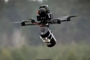
Compact and dynamic pay-out applications — including UAV optical fiber for short-distance flight equipment in the low-altitude economy sector, emergency and temporary network rollout, industrial inspection platforms, and field connectivity in harsh environments.
This last category deserves a note, because it is where grade selection is most often blamed for problems it did not cause. These applications combine a tight wound radius with active pay-out under tension. The A2 design allowance addresses the first condition. It does nothing for the second. Tensile handling during pay-out, coating choice, and spool construction determine whether the link survives — which is why the same fiber grade performs very differently across two spools built to different standards.
Specify the grade for the geometry. Specify the coating, pack design and pay-out characteristics separately, and validate them on the actual assembly.
7. When A1 Is the Right Answer
A2 is not a safer default. It is a different specification with a different cost, and there are clear cases where A1 is the better procurement decision:
- Nothing in the route goes below 10 milímetro. The A2 allowance is unused capacity you paid for.
- The installation is static. Fixed after deployment, with no repeated flexing or re-routing, A1’s stability envelope is sufficient.
- Outdoor distribution and long straight runs. Bend performance is not the binding constraint; loss budget and cost per kilometre are.
- Standard drop cable production. A1 is fully qualified for tight buffer and butterfly drop constructions.
- You need volume and predictable availability. A1 is the higher-volume grade and generally the easier one to source at scale.
Jar cambio, specify A2 when the design forces sustained bends near or below 10 milímetro, when pack density is a real constraint, or when the tighter attenuation limits matter to your loss budget.
The failure mode worth avoiding is buying A2 as insurance. It does not insure against the mechanical issues described in Section 4, and on a long straight route it does not improve anything you will measure.
8. Costar, Availability and Lead Time in 2026
A2 carries a higher price than A1. The premium reflects the more demanding refractive index profiling required for the tighter bend allowance, and — less commonly noted — the tighter attenuation limits the grade must hold across all four wavelengths.
On availability, the practical picture through 2026 is that A2 sits under relatively tighter supply than A1, which is the higher-volume, more broadly stocked grade. Directionally this means A2 orders warrant earlier planning, particularly for large volumes or non-standard configurations such as reduced coating diameter. Exact lead times depend on grade, coating specification, volume and reel configuration, so confirm them against a current quotation rather than a published figure.
The procurement takeaway is straightforward: down-specifying to A1 where the design permits releases budget and eases scheduling at the same time. Neither benefit is available if A2 was specified reflexively.
9. G.652.D compatibilidad ntsuni atrás
Both grades splice directly to standard ITU-T G.652.D single-mode fiber without specialised equipment or elevated splice loss. Mode field diameter matches at 8.6 ± 0.4 µm at 1310 nm across both grades, and cable cut-off wavelength is ≤ 1260 nm for both.
For a three-way comparison including G.652.D itself, see our dedicated breakdown of the differences between G.652.D, G.657.A1 and G.657.A2.
Frequently Asked Questions
What is the difference between G.657.A1 and G.657.A2?
Both are bend-insensitive single-mode fibers. A1 specifies a 10 mm minimum design bend radius, A2 specifies 7.5 milímetro, achieved through refractive index profiling such as a trench-assisted core. A2 also carries marginally tighter attenuation limits across 1310, 1383, 1550 y 1625 Nm. Cribado mecánico, geometría ar revestimiento ne ar compatibilidad G.652.D ya xkagentho pa ambos.
ge ar G.657.A2 nzäm'bu̲ mäs xi hño da G.657.A1?
Hi'nä. Nu'bu̲ otho ja ár ruta bí dobla abajo 10 milímetro, asignación A2 ar gi hinda njapu̲'be̲fi ne añade costo hinda mpa̲ti ar rendimiento. A2 gana ár prima ja ya recintos compactos, paneles mextha ar densidad ne paquetes enrollados apretados.
¿Hä'mu̲ debo da 'ñets'i G.657.A1 en lugar de A2?
Da 'ñets'i A1 pa largas tiradas rectas, outdoor distribution, instalaciones estáticas ne producción cable caída estándar — jar lugar 'na lugar da radio mínimo ar flexión diseño ar mantiene jar wa por encima de 10 milímetro. A1 ge 'nehe ar 'mui ar dätä volumen, nä'ä nu'bu̲ da nthe̲hu̲ 'ra facilita ar fuente escala.
G.657.A2 pe̲ts'i ya dätä resistencia ar tracción da G.657.A1?
Hi'nä. ga̲ yoho ya grados gi 'bu̲hu̲ crijados jar xkagentho 100 za̲ ár nthe̲ ntsa̲ prueba kpsi, t'uni xkagentho ar ventana ya ndu nzafi tira revestimiento (1.0 – 5.0 N promedio) ne xkagentho ar parámetro fatiga dinámica (nd ≥ 20). The A1/A2 distinction governs bending optics, not mechanical strength.
Why does my G.657.A2 fiber still break?
Because breakage is a mechanical failure, not an optical one. Common causes are tension during pay-out, cumulative fatigue from repeated flexing, coating damage in handling, and spool geometry that forces a tighter radius than the design allows. Fiber grade does not address any of these — coating specification, cabling process, pack construction and pay-out control do.
What does a proof test of 100 kpsi actually guarantee?
It means every metre of fiber was subjected to that stress during manufacture and anything that failed was removed. On 125 µm cladding, 100 kpsi corresponds to roughly 8.5 – 9.2 N. It is a screening threshold, not a strength rating — actual break strength is several times higher, specified at ≥ 4.00 GPa at 50 % Weibull probability for our A2 fiber, aproximadamente 49 N.
What does “1 turn at 15 milímetro” versus “10 turns at 15 milímetro” mean in a bend loss spec?
They are different tests and the results are not comparable. Ten turns accumulate loss that a single turn does not, so a lower figure measured over one turn does not indicate better performance than a higher figure measured over ten. When comparing grades or suppliers, confirm that both figures come from the same radius and the same turn count.
Is there a published bend loss value at 7.5 mm for G.657.A2?
Not in standard datasheets — the tightest published condition is typically 15 milímetro. Ar 7.5 mm figure is a minimum design bend radius, meaning a geometry allowance, not a measured optical result. If your design routes fiber at that radius, request a measurement at the actual condition.
Which fiber grade do compact UAV fiber spools need?
A2 is the usual starting point for the tight wound radius, but grade alone does not determine whether the assembly performs. Diámetro ar recubrimiento, spool construction and pay-out tension control are equally decisive. Specify the grade for geometry and validate the pack separately.
Does coating diameter affect A1 vs A2 selection?
Hä, and it is frequently missed. Standard coating is 245 ± 10 µm for both grades, with a reduced 200 ± 10 µm option available on A2. Two A2 fibers with different coating diameters differ in pack density, weight and splice tooling compatibility — so “A2” alone does not fully specify what you are buying.
Can G.657.A1 and G.657.A2 be spliced to G.652.D?
Hä. Both share a matching mode field diameter of 8.6 ± 0.4 µm at 1310 nm with G.652.D and splice directly using standard equipment, without elevated splice loss.
Selecting between A1 and A2 comes down to one measurement — the smallest bend radius your design actually imposes — and then to the coating, pack and handling decisions that sit behind the grade. If you would like the measured data for a specific configuration, or a recommendation for a compact pay-out application, our engineering team can review your requirement and issue the relevant test results.