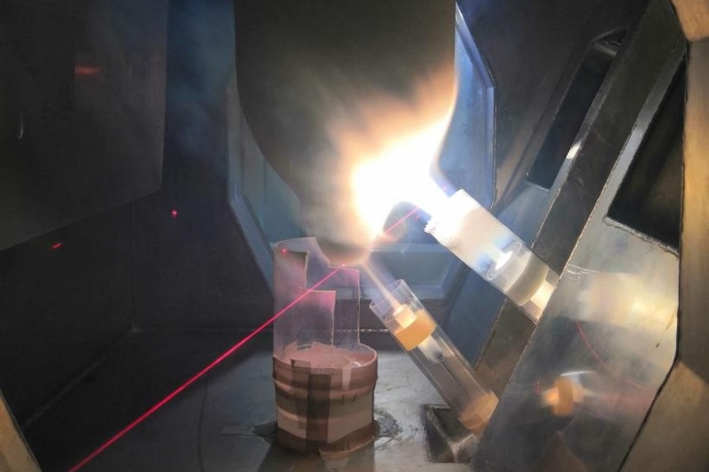
Optical fiber cable quality does not start at the cable extrusion line. It starts much earlier, with the glass chemistry, the preform, the drawing tower, the coating system, and the test discipline behind every reel of fiber.
That matters because two cables can share the same fiber type name and still behave differently in the field. One splices cleanly, holds low attenuation, survives tight FTTH routing, and gives stable OTDR traces. The other creates small failures that installers only discover after deployment.
The difference often comes from the upstream optical fiber manufacturing process.
This guide explains how modern optical fiber is made from raw materials to final fiber, and how each manufacturing stage affects the cable that buyers eventually install.
The optical fiber manufacturing process in one chain
| ដំណាក់កាល | What happens | Why it matters to the final fiber |
| Raw materials | High-purity silica and dopants are prepared for glass formation | Impurities create attenuation and water-peak risk |
| Preform production | A large glass rod is built with the same optical structure as the final fiber | The preform defines the fiber’s optical DNA |
| Fiber drawing | The preform is heated and pulled into 125µm bare glass fiber | Drawing stability controls diameter, strength and consistency |
| ថ្នាំកូត | UV-cured polymer layers protect the fresh glass | Coating quality affects microbend resistance and handling reliability |
| Quality testing | នៃរេក្យងឆ្លុហស្បុង, geometric and mechanical properties are measured | Test reports prove whether the fiber is ready for cabling |
| Cable integration | The tested fiber enters loose tube, tight buffer, drop cable or other cable structures | Cable design protects the fiber but cannot rewrite its upstream quality |
The chain is unforgiving. A cable factory can add better sheath material, stronger aramid yarn, water blocking or armor, but it cannot remove impurity from the glass or correct a poor refractive index profile after the fiber has already been drawn.
Raw materials: purity becomes attenuation
Most optical fiber starts with high-purity chemical precursors. ស៊ីលីកុន tetrachloride (SiCl₄) forms the silica base. Germanium tetrachloride (GeCl₄) raises the refractive index in the core. Fluorine-containing dopants can lower the refractive index in selected glass regions.
The goal is not just to make transparent glass. The goal is to make glass that carries light over long distances with predictable loss.
Small contamination matters. Transition metals absorb light. Hydroxyl groups (OH⁻) create absorption around the 1383nm water peak. Moisture control, precursor purity and dehydration discipline therefore influence attenuation before the preform even becomes a fiber.
For a cable buyer, this upstream chemistry explains a common pricing gap. Two fibers may both claim a familiar standard, but one comes from a more tightly controlled glass process. That difference may show up later as lower attenuation margin, more stable long-distance transmission, or fewer unexplained reel-level issues.
Preform production: the optical DNA of the fiber
An optical fiber preform is a large glass rod with the same core-cladding relationship and refractive index profile as the final fiber. During drawing, that structure scales down to a 125µm bare fiber. The tower changes the size, not the optical design.
That is why the preform is the highest-barrier part of the chain.
The preform determines or heavily influences:
- ការកាត់បន្ថយ
- ការបែកខ្ញែក
- Cutoff wavelength
- Mode-field behavior
- Multimode bandwidth potential
- Core-cladding concentricity
- Drawable length and tower changeover frequency
Modern preform production is usually two separate jobs. The first is core rod manufacturing, which sets the optical performance. The second is overcladding, which builds the final preform diameter and affects manufacturing cost and geometry.
អ្វី, OVD, PCVD and MCVD all appear in the industry, but they do not serve the same purpose. VAD and OVD are common routes for standard singlemode production. PCVD is strong in complex refractive index profiles such as high-end multimode fibers. MCVD still serves specialty fiber designs where precision matters more than volume. For a deeper method-level comparison, ឃើញ វិធីសាស្រ្តនៃការផលិត Fiber Optic Preform.
For manufacturers and new line investors, this is also where supplier capability becomes serious. A company that only buys finished fiber and cables it is not controlling the same part of the value chain as a company that can support preform supply and drawing-tower setup.


គំនូរ: turning preform into 125µm fiber

The fiber drawing process starts when technicians load the finished preform into a vertical draw tower. A high-temperature furnace softens the preform tip, and the molten glass is pulled downward into a continuous fiber strand. The industry-standard bare glass diameter is 125µm.
Drawing is where a stable preform becomes either a stable fiber or a long run of hidden risk. Furnace temperature, draw speed, ភាពតានតឹង, cooling and online diameter control all matter. If the process swings, diameter variation, surface flaws and coating instability follow.
Coating and microbend protection
Freshly drawn glass is strong in theory and fragile in the real world. Before it touches any guide surface, the fiber passes through coating dies and UV curing systems. The coating usually has two layers.
The primary coating is softer. It cushions the glass and absorbs microbending stress. The secondary coating is harder. It protects the fiber during handling, cabling and installation.
Traditional fibers often use a 250µm coated diameter. High-density cable designs may use 200µm fibers to fit more fiber count into less space. Neither is automatically better. A 200µm fiber can support compact cable designs, but it leaves less mechanical margin for poor coating control or harsh processing. A 250µm fiber gives more established handling tolerance, though it costs space in high-density constructions.
| Coating choice | សមល្អបំផុត | Buyer concern |
| 250µm coated fiber | Standard telecom cable, broad handling tolerance | Larger cable diameter at high fiber counts |
| 200µm coated fiber | High-density cable, space-limited designs | Requires disciplined coating and cabling control |
| Bend-insensitive fiber with coating system | FTTH, indoor routing, tight bends | Verify bend-loss data, not just fiber type name |
Ask for coating diameter, coating concentricity, cure control and stripping performance. Also ask whether the same fiber type has been used in the cable structure you plan to buy. A fiber that tests well alone can still suffer if the cable design induces microbending.
ការធ្វើតេស្តគុណភាព និងនិន្នាការផលិតកម្ម
Testing is where supplier claims become evidence. A credible fiber supplier should not only say the fiber meets G.652.D, G.657 or multimode requirements. It should show batch-level reports.
| Test item | What it reveals | Buyer verification question |
| Attenuation at 1310nm and 1550nm | Transmission loss for singlemode fiber | What is the measured value by batch, not only the limit? |
| Water peak / 1383nm loss | OH contamination and dehydration quality | Is low-water-peak performance verified for this lot? |
| Geometry: cladding diameter, non-circularity, core concentricity | ការបំបែក, connectorization and consistency | Can you provide the geometry report for the drawn fiber? |
| អង្កត់ផ្ចិតវាលរបៀប / cutoff wavelength | G.652/G.657 design compliance | Which standard and test method apply? |
| Bend-loss test | FTTH and tight-routing reliability | What loss is measured at the specified bend radius? |
| ការធ្វើតេស្តភស្តុតាង | Mechanical screening for weak points | What proof level is used before shipment? |
| Coating diameter and strip force | Cabling and termination behavior | Has this coating been validated with our cable process? |
| OTDR trace or reel report | Reel-level continuity and event detection | Can you provide reel-by-reel documentation? |
For G.652.D singlemode, the current page states attenuation examples of ≤0.33 dB/km at 1310nm and ≤0.19 dB/km at 1550nm. For G.657 bend-insensitive fiber, it mentions macrobending tests at 5mm or 7.5mm radii. These are useful reference points, but publish them as standard-linked targets only if your team can confirm the exact standard, test method and scope.

Fibconet’s role in the manufacturing chain
Fibconet serves cable-side buyers and upstream manufacturing projects from different angles.
On the cable side, Fibconet supplies fiber optic cable products for FTTH, indoor and outdoor network applications. On the upstream side, Fibconet’s preform equipment page describes optical fiber preforms, optical fiber draw towers and support for complete fiber production lines.
This does not mean every project uses the same supply model. Preform type, drawing capacity, អង្កត់ផ្ចិតថ្នាំកូត, target fiber standard and testing requirements should be confirmed project by project. But it does mean Fibconet can discuss optical fiber quality before the cable stage, which is valuable for manufacturers, new plant investors and buyers who want more than a finished-cable quotation.
If your project involves upstream fiber production or a new draw line, start with គ្រឿងបរិក្ខារពីរោងចក្រ Fiber Optical Preform. If your project focuses on cable procurement, continue with Fibconet’s ក្រុមហ៊ុនផលិតខ្សែកាបអុបទិក page.
សេចក្តីសន្និដ្ឋាន
The optical fiber manufacturing process is a chain, not a single machine. Raw material purity becomes attenuation. Preform quality becomes optical performance. Drawing stability becomes dimensional and mechanical consistency. Coating becomes microbend protection. Testing becomes the buyer’s evidence.
Cable quality starts long before the cable is made.
That is the main reason upstream manufacturing knowledge matters. When you understand the process from preform to final fiber, you can compare suppliers more intelligently, explain price differences more convincingly, and choose fiber optic cable with fewer hidden risks.