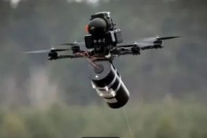
A drone fiber link fails in flight, and the first question is almost always about the fiber grade. Was it really G.657.A2? Did the supplier ship something cheaper?
That question rarely leads anywhere, because the bend grade governs how much light survives a tight bend. It says nothing about whether the glass survives being pulled off a spool at speed. Payout breakage is a mechanical event, and the specifications that predict it are usually missing from the conversation entirely.
This guide covers where the fiber actually fails, how to read a tensile strength number without being misled by it, why reel construction matters as much as the fiber, and what to write into a specification so the next batch can be judged against something concrete.
Quick Mhinduro: The Three Numbers That Decide Whether Your Fiber Survives
| Number | Zvarinokuudza | Typical value for FPV-grade bare fiber |
|---|---|---|
| Proof test level | The screening stress every metre passed during manufacture | ~100 kpsi (≈ 8.5–9.2 N on 125 µm cladding) |
| Kusimba simba | The load at which the fiber actually breaks | ~50 N typical; 55–60 N for enhanced versions |
| Payout tension | The load the reel imposes while unwinding at flight speed | Not published by anyone — you have to test it |
The third number is the one that ends flights, and it is the one no datasheet contains. It comes from reel construction, winding method and how fast the drone accelerates, not from the fiber specification.
If you read only one thing here: a fiber with excellent tensile strength on a badly wound reel will still break. The reel is not packaging.
Where Drone Fiber Actually Fails
Payout failures fall into four mechanisms. They call for different fixes, and treating them as one problem is why the same failure keeps recurring.
Static break
The fiber is pulled beyond its tensile limit in one event — a snag on an obstacle, an abrupt directional change, a catch on the airframe. Load spikes past the break threshold and the link is gone instantly.
This is the mechanism people picture, and it is the least common of the four.
Dynamic payout break
Tension builds while the fiber unwinds. A reel that releases unevenly, a layer that catches on the one beneath it, an acceleration faster than the pack can feed — each drives tension upward, and glass fails at whatever load it reaches, which can be well below its rated strength if a defect happens to sit at that point.
This is the dominant failure mode in flight, and it is governed by the reel far more than by the fiber.
Abrasion and friction damage
The fiber rubs against the reel edge, the housing exit, or itself. The coating wears, the glass surface picks up microscopic damage, and strength drops locally. The break may happen minutes later somewhere that looks unremarkable.
Friction damage is cumulative and invisible, which makes it the hardest mechanism to diagnose after the fact.
Tangling and self-fouling
The fiber loops back on itself, catches the airframe, or forms a knot as it comes off the pack. A knot in optical fiber concentrates stress at a radius far below anything the grade allows, and it breaks there.
Sei “it broke” is almost never a grade problem
Three of these four mechanisms are decided by the reel and by flight profile. The fourth — static break — depends on tensile strength, and tensile strength is not what thebend-insensitive grade describes. A1 and A2 are screened to the same mechanical level and differ in bending optics.
So when a supplier confirms the fiber really is A2 and the breakage continues, that is the expected outcome, not a contradiction. For background on how the tethered architecture works and what it costs you, see our guide to thefiber optic FPV drone.
How to Read a Tensile Strength Number
Here is the practical problem. Two suppliers quote tensile strength. One says 50 N, another says 500 N. The second looks ten times stronger.
Very often it is not stronger at all — it is measuring something else. A tensile figure is meaningless until you know three things about it.
Mubvunzo 1: What was tested?
Bare fiber, tight-buffered fiber and cabled fiber are three different products with three different strengths.
| What is being tested | What carries the load |
|---|---|
| Bare fiber (245 µm or 200/242 µm coated glass) | The glass itself |
| Tight-buffered fiber | Glass plus buffer layer |
| Cabled fiber | Aramid yarn, FRP or steel strength members — the glass carries almost none of it |
A cabled construction can be rated in the hundreds of newtons because aramid yarn carries the load. That number is real for the cable, and irrelevant to bare fiber on a drone reel.
A quick check: if a tensile figure appears alongside words like aramid, nhengo yesimba, or reinforced, it is describing a cable. Bare fiber has none of those components. When a bare fiber page quotes a strength that could only come from a reinforced construction, the number and the product do not match.
Mubvunzo 2: How was it tested?
Proof test and tensile strength are different measurements, and the gap between them is large enough to look like an error when it is not.
- Proof test — every metre of fiber is subjected to a defined stress during manufacture. Anything that fails is removed. This is a screening threshold, not a strength rating.
- Kusimba simba — the load at which the fiber breaks, usually reported as a Weibull distribution because glass strength is statistical rather than a single value.
The next section covers why they differ by roughly six times.
Mubvunzo 3: What unit?
Fiber strength appears as newtons, GPa or kpsi depending on the datasheet, which makes specs look incomparable when they are not. All three convert freely, because stress is force divided by cross-sectional area.
For standard 125 µm cladding:
A=πr2=π×(62.5×10⁻⁶)2=1.227×10⁻⁸ m2
Force(N)=Stress(Pa)×A1 GPa=145 kpsi
Which gives:
| Stress | Force on 125 µm cladding | Equivalent |
|---|---|---|
| 0.69 GPa | 8.5 N | 100 KSI |
| 3.20 GPa | 39.3 N | 464 KSI |
| 4.00 GPa | 49.1 N | 580 KSI |
And in reverse:
| Force | Stress | Equivalent |
|---|---|---|
| 9.0 N | 0.73 GPa | 106 KSI |
| 50 N | 4.07 GPa | 591 KSI |
| 60 N | 4.89 GPa | 709 KSI |
Keep that first constant and you can convert any fiber strength spec yourself.
Muenzaniso wakashanda: reading a real datasheet
Take a bare fiber datasheet listingProof Test ≥ 9.0 N / ≥ 100 kpsi uye, elsewhere on the same page, a headline figure of several hundred newtons.
Run the three questions:
- What was tested? The proof test line is bare fiber. A several-hundred-newton figure on 125 µm glass converts to tens of GPa — above the theoretical strength of silica. It cannot describe bare fiber, so it is describing a reinforced construction.
- How was it tested? 9.0 N is a screening threshold. The headline figure, whatever it belongs to, is a break load. Different measurements.
- What unit? Both in newtons, so the units are not the discrepancy.
Two figures on one page, describing two different products. Neither is necessarily false — but they are not comparable, and only one of them is the fiber going onto your reel.
Do this before comparing quotes and the comparison becomes possible. Skip it and you will choose on a number that describes a cable you are not buying.
Proof Test vs Tensile Strength
What proof testing actually does
Proof testing pulls the entire length of fiber to a defined stress during manufacture. Its purpose is elimination, not qualification: any point weak enough to fail at that stress breaks in the factory rather than in your reel.
A 100 kpsi proof test therefore guarantees a floor. Every metre survived 0.69 GPa, roughly 8.5 N. It does not mean the fiber breaks just above that.
Why the two numbers differ by roughly six times
Actual break strength sits well above the screening level. Our A2 fiber specifies ≥ 4.00 GPa at 50 % Weibull probability — about49 N — with typical values around50 N, and enhanced versions measured at55–60 N.
So the same fiber legitimately carries a 100 kpsi proof test rating and a ~50 N tensile strength. The ratio is about5.9×, and it is designed in:
| Value | Basa | |
|---|---|---|
| Proof test | ~8.5 N (100 KSI) | Screening floor — every metre passed |
| Kusimba simba | ~50 N (4.07 GPa) | Typical break load |
| Enhanced tensile | 55–60 N | Measured on enhanced versions |
Reading the first number as the second makes fiber look six times weaker than it is. Reading the second as the first makes a screening threshold look like a performance guarantee. Both mistakes appear regularly in procurement discussions.
What this means for your spec: ask for both. Proof test tells you the manufacturing floor; tensile strength tells you the working margin.
Reel Design: Why Internal Winding Matters
The fiber specification sets an upper bound on what the link can survive. The reel decides how much of that margin you actually get.
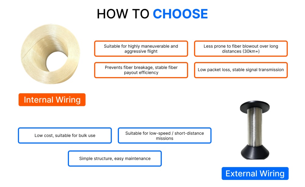
Internal vs external winding
External winding leaves the fiber on the outside of the reel body, exposed to the housing, the airframe and anything the drone brushes past. Every exposed turn is a potential abrasion point.
Internal winding keeps the fiber inside the housing during release. The pack is protected from external contact, and the fiber leaves through a controlled exit path rather than peeling off an open surface.
The mechanism is straightforward: fewer external contact points, less friction, fewer places for the fiber to catch during dynamic release. This matters most on the failure mode that causes the most flights to end early — dynamic payout break, where tension spikes come from irregular release rather than from any single obstacle.
Reel material and weight
Reel mass is carried for the entire flight, so it competes directly with battery and payload.
3D-printed ABS housings suit this application for reasons beyond weight: geometry can be matched to a specific airframe, and revisions do not require new tooling. That makes them well suited to prototyping and to platform-specific builds. Injection moulding becomes more economical at higher volumes, at the cost of tooling lead time and design lock-in.
The engineering point is that reel geometry — barrel diameter, flange spacing, exit path — is a design variable that should be matched to the platform, not accepted as whatever the supplier stocks.
Resin coating and friction
An optional resin layer over the wound pack reduces friction between adjacent turns and adds a measure of protection during handling. It also adds mass.
Whether it is worth the weight depends on the platform. Aggressive acceleration profiles, where inter-layer friction is most likely to spike tension, benefit most. Slow controlled deployment may not need it. Ask your supplier which they recommend for your specific speed profile rather than treating it as a universal upgrade — and note that reducing the coating diameter, which changes both pack density and weight, interacts with this decision.
Payout Speed and the Tension Window
Every reel has a speed range within which the fiber releases cleanly. Below it, slack can accumulate and loop. Above it, tension rises until something fails.
That window is a property of the assembly — fiber, winding pattern, reel geometry and exit path together — which is why no fiber datasheet can tell you what it is. It has to be measured on the actual pack.
How to establish it:
- Run pay-out on the bench across your intended speed range, with the reel mounted as it will be on the aircraft.
- Watch for the two failure signatures: hesitation or jerking (a layer catching) and slack accumulation (releasing faster than the drone advances).
- Note the speed at which either appears. Your operational ceiling sits below it, with margin.
- Repeat after any change to reel geometry, winding method, coating diameter or fiber length.
Aggressive acceleration is the most common way to exceed the window in flight. A profile that works at a steady climb may fail on a fast departure, and that difference will not appear on any specification sheet — only on the bench.
Also relevant to theminimum bend radius the pack imposes: a tightly wound reel holds the fiber near its bending limit for the entire flight, not just at the moment of release.
Urefu, Weight and Flight Time
Reel length is a three-way trade, and optimising any one variable costs you the other two.
- More fiber means longer potential range and a heavier pack.
- A heavier pack means shorter flight time and reduced payload capacity.
- Shorter flight time means less of that theoretical range is reachable.
Beyond a certain length the added fiber cannot be used within the remaining endurance, so the practical answer is to size the reel to your mission radius plus margin, rather than to the maximum the platform can lift.
Coating diameter enters here as well. A reduced coating puts more length on the same reel at lower weight, at the cost of a thinner protective layer and different handling behaviour. Whether that trade is worth making depends on the platform and on how much handling the fiber sees before flight — the mechanical characteristics of reduced-coating fiber should be requested specifically rather than assumed from the standard datasheet.
What to Put in Your Specification
Most drone fiber specifications describe the fiber and stop, which leaves the parts that determine payout survival entirely to the supplier’s discretion. These lines make a batch verifiable.
Fiber
- Fiber grade and the ITU-T category it complies with
- Coating dhayamita, stated explicitly (200/242 µm or 245 µm — do not leave it implied)
- Proof test level, in kpsi or N, with the unit stated
- Kusimba simba, stated separately from proof test, with the measurement basis (normal, or Weibull probability level)
- Attenuation at your operating wavelengths
Reel
- Winding method: internal or external
- Reel material and total wound weight
- Fiber length per reel, with tolerance
- Reel geometry: barrel diameter and exit path configuration
- Resin kupfeka: required, optional, or not required
Verification
- Per-reel OTDR trace and attenuation record
- Pay-out test evidence at your intended speed range
- Batch traceability from reel to fiber lot
Two clauses worth adding explicitly:
Tensile strength shall be stated for bare fiber, not for a cabled or reinforced construction.
Proof test level and tensile strength shall be reported as separate values.
Those two lines make it impossible to answer your specification with a number that describes something you are not buying.
How to Verify Before Acceptance
On documentation. Request the per-reel OTDR trace and attenuation record. OTDR shows attenuation along the full length and reveals point discontinuities that a single end-to-end measurement will not catch. Check that the trace corresponds to the reel you received, not to a batch sample.
On the reel itself. Inspect the wind before mounting. Look for crossed layers, uneven tension between layers, and any point where the fiber sits against a sharp edge. A visibly irregular wind will pay out irregularly.
On the bench. Run the pay-out test from the previous section before the first flight, not after the first failure. This is the only test that exercises the actual mechanism that ends flights, and it costs one reel of your own time rather than one aircraft.
Across batches. Keep the OTDR records. When a failure does happen, the difference between a reel that met spec and one that did not is only visible if you have the earlier records to compare against.
Fibconet supplies bend-insensitive bare fiber and wound reels for civil and industrial field communication — emergency response, industrial UAV inspection, search and rescue, and temporary network deployment. Tensile level, kuvhara dhayamita, resin coating, reel design and per-reel OTDR reporting are specified per platform; maona G657A2 FPV drone fiber on 3D-printed ABS reel for the material specifications, or send us your platform parameters and payout speed range and our engineering team will review them against measured fiber data.